|
|
|
||||||
|
Angotti Product Deveopment Newsletter Volume 7, No. 3 (Click Here for pdf Version) "Helping You Accelerate Your High-Tech Development Projects" Welcome to the ANGOTTI PRODUCT DEVELOPMENT e-mail newsletter! The goal of this newsletter is to help you accelerate your development projects by sharing many of the tips, techniques, and strategies we've honed during three decades of providing high-tech consulting services. A Semi-Automatic Tester Designed for Final Production By Carl Angotti, Angotti Product
Development, https://www.angotti.com Introduction Semi-Automatic Final Functional Testers sit in the tester spectrum between a 100%-manual tester and a 100% automatic tester. Differences among them are described in the next section. The primary tradeoff is how much or little is available to spend on the tester, balanced against the impact of the device selling price and sales volume. The more automated a tester is, the lower the cost to perform the testing. Of course, a highly automated tester is the most expensive to create. To contrast the types of testers from one another can generally be described as follows: A manual tester s dominated by the testing having the Test Operator almost exclusively doing all of the UUT (Unit Under Test) testing manually. The Operator follows a detailed written test procedure and manually records test results. Frequently,
this tester style has the Operator set up the test equipment for each
test and then read and record the results or indicates pass or fail for
a particular test. There is also special cabling for such a tester, and
sometimes a manual switch array is used to help speed testing. See the
APD (Angotti Product Development) paper at https://www.angotti.com/docs/040921_EZine.html
for an example of such a tester. If
the UUT contains one or several embedded controllers, the tester most
certainly is at least semi-automated one. For such a tester, Also, the
Operator needs at least some skill to read and interpret the
measurements. The
operator test costs for such testers sits between those of a manual and
fully automatic tester. The test speed is slower, and the test quality
is somewhat lower than an automated tester, but tester development
costs are much less than with a fully automated tester. Reasons
for selecting a Semi-Auto approach Such a test approach is warranted if the UUT has multiple microcontrollers plus lots of inputs and/or outputs. The PC test program can present commands to the system, and the Operator doesn’t have to be burdened with manually entering these commands into the system. The Operator can then read the respective outputs to determine system test staus. Some of the outputs might be automatically monitored and tested for Pass/Fail criteria via the test program. Lack of Test Points necessitates manual probing by the Operator internal to the system. Further complicating testing is that sometimes there is no automatic way to assess the results of a test due to a lack of automatic instrumentation or the lack of ability for a test instrument to interpret the test results correctly.Under the conditions mentioned above, a Semi-Automated tester is a correct choice. Generic
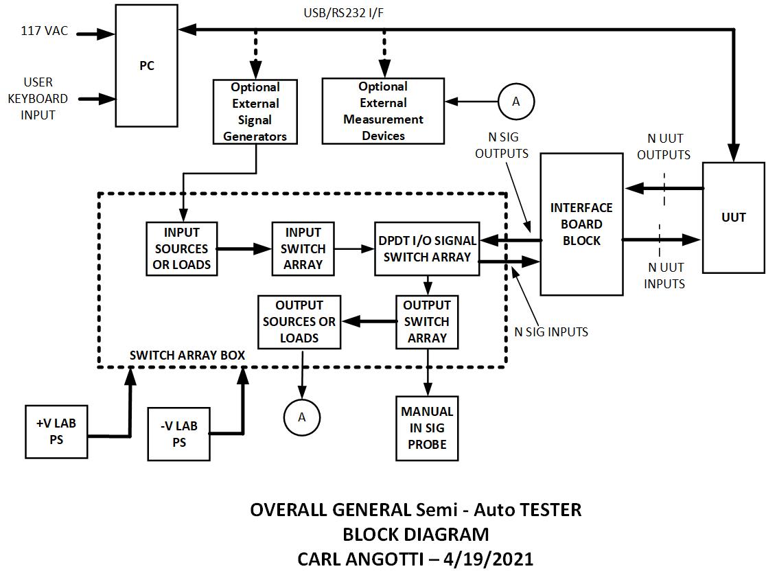
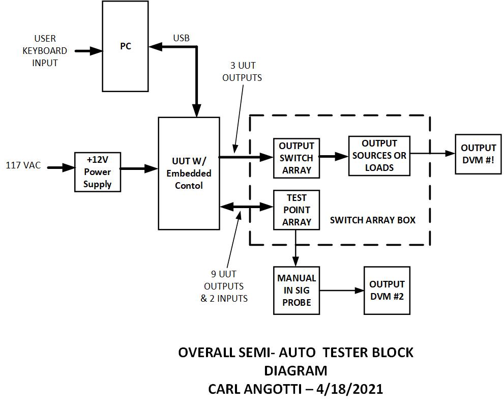
Semi-Auto Tester Block Diagram The block diagram below illustrates a generic form of a semi-automatic tester. It shows an advancement over a manual tester. In this case, the PC communicates with an embedded controller in the UUT and can receive responses. The optional External Signal Generators or Measurement Devices can either be manually set and read or automatically set and read via a USB port. There is assumed to be some automatic and some manual testing done by the test procedure running on the PC and some testing done by the test operator. Semi-Auto Tester Block Diagram Example The
block diagram below illustrates the system interconnections at the
block diagram level of an example tester APD designed to test an
in-company product. Note that it contains a simple switch array inside
the switch array box. The system had only a few fixed signal inputs and
nine measurement outputs. Some of these outputs are generated by the
UUT, and some are done via hand probing.
The interface connectors and inputs come from a system interface connector custom-made for this UUT. All output signal measurements are done via one of two DVMs and are read by the Operator and recorded via the PC operator interface. This recording is accomplished in the same way described in the earlier Manual Tester article. The changes that occur are in the script code sent to the UUT. Operator readouts were done via two auto-ranging DVMs. One monitored a voltage output, and another utilized a manual probe to verify internal voltages on the board and the switch array box. This example tester is designed to meet the needs of a specific client. It was designed to test boards that have a maximum production rate of 15 per month. A standardized test procedure facilitated the testing via a unique piece of software that guided the testing. This software allows the Operator to indicate pass or fail. A unique input text file was generated to guide test steps. This input text file utilizes a small set of script commands to serve as the procedure. The test results are then recorded in an archival output file for later review.
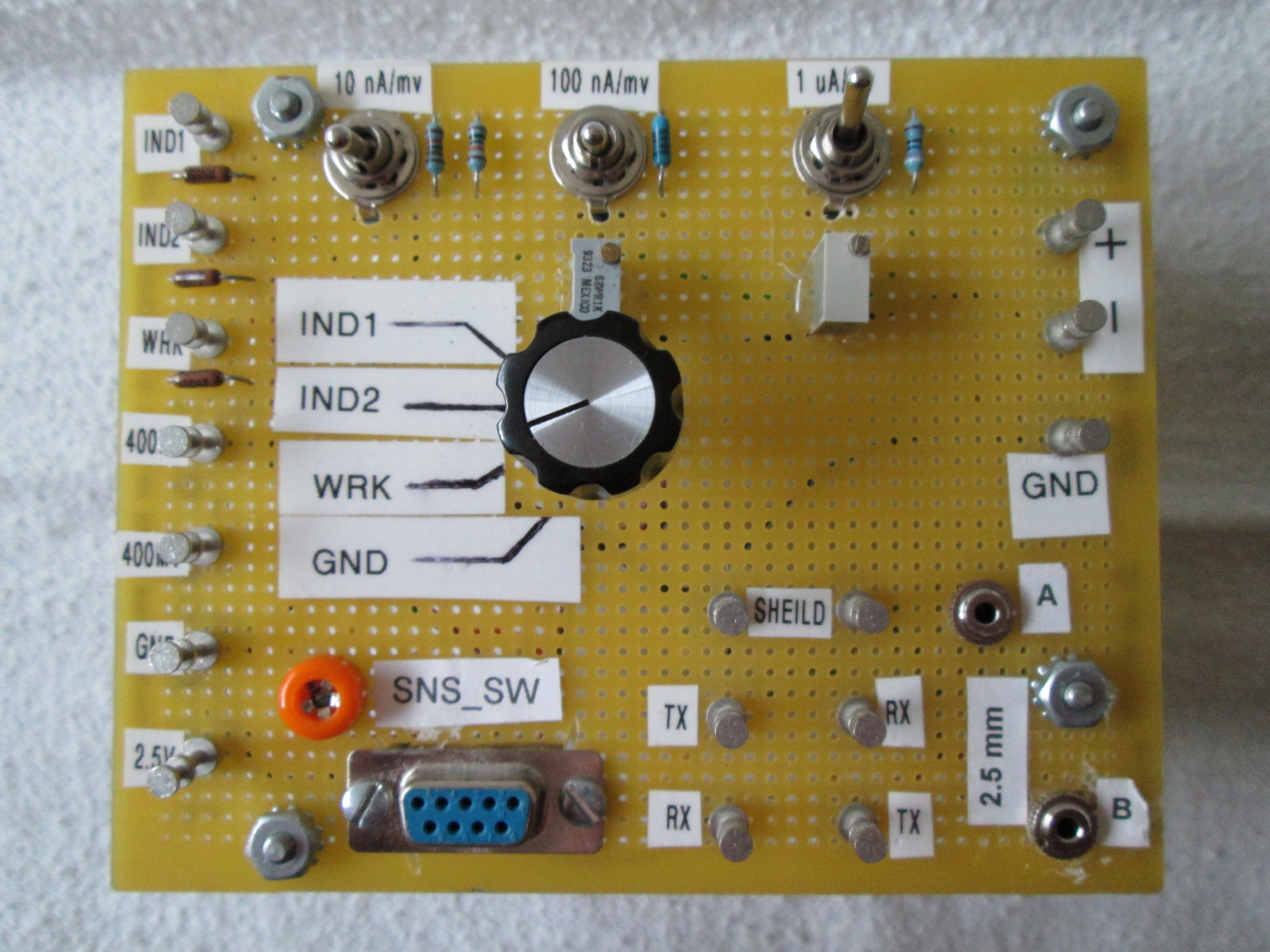
Illustration of the Test Interface Box An illustration of the test interface box that was used appears below. It contains the input switch, along with the large test points used to test the UUT.
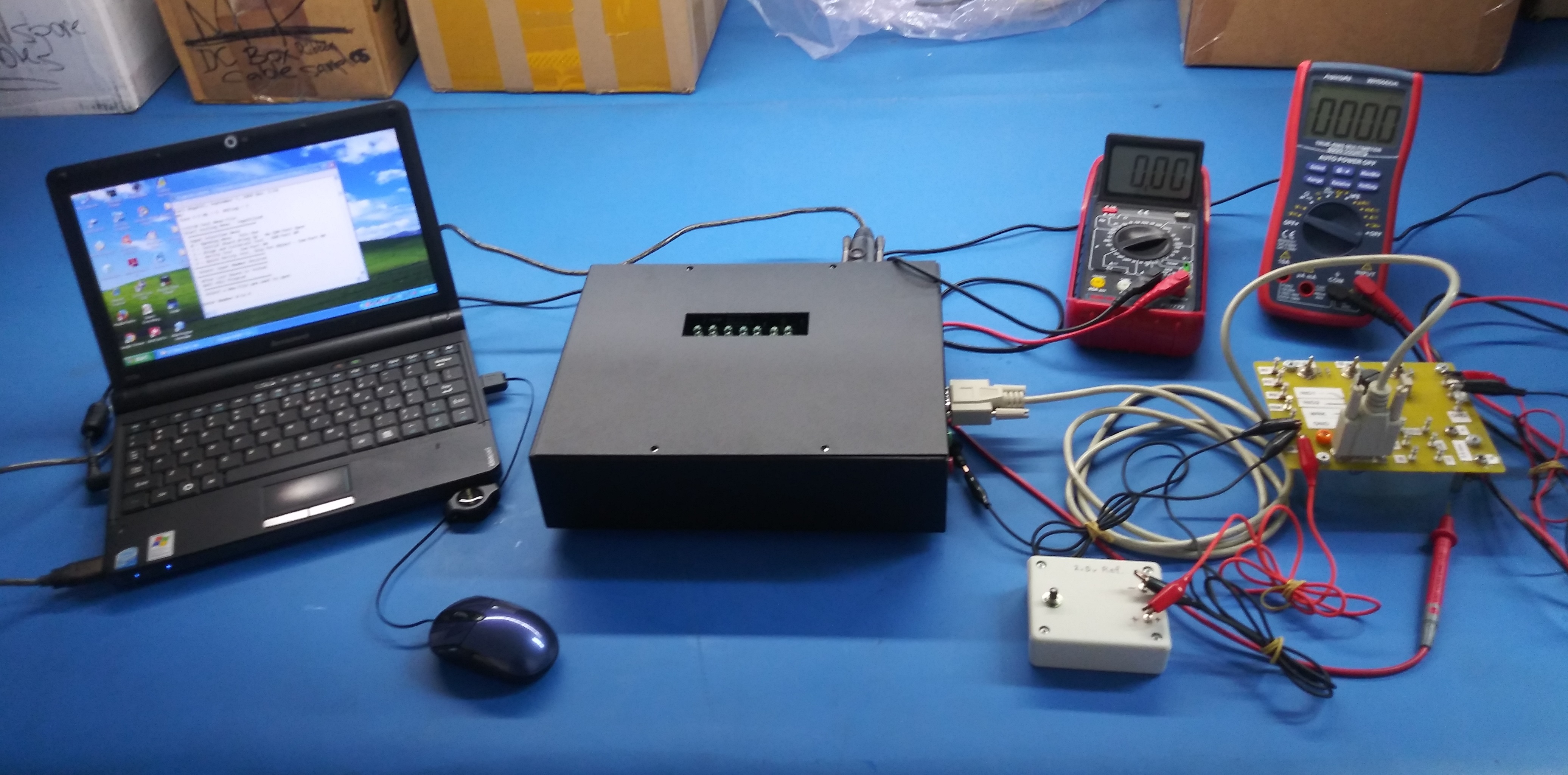
Illustration of the UUT under Test A picture of the actual UUT System assembly under test using the actual tester is shown below.
Semi-Auto Testing the UUT The
unit under test sequence using a Universal Basic test code executable
is described here. Testing is accomplished utilizing a unique PC test
control program. The test process is described in this section. Input Test Code Snippet The
snippet below illustrates the form of the Input file commands from the
text file that controls the program via the PC executable. It
illustrates the simplicity of entering tests to the Operator for
semi-automatic testing. This text file is the formalized Test Procedure
that the Test Engineer creates. The code is broken into Sections
(Groups) that can be skipped by the Operator if desired to advance more
quickly to a particular set of tests.
To make the input text more understandable, comments were added to the actual procedure file. These comments appear in the snipped example below just to the right of the "<<. " Note: A complete set of test script commands is available by emailing carl@angotti.com. '4/7/21 - InputFile3 Open
<< Printed Comment to Operator
' *************************** ' Start Formal Board Testing ' All Tests Do Not Use Com Port '**************************** CC Check to see if ComPort is Open << “CC” is a Special Test Sometimes Required to support testing '**************************** 'Test the XY 16880 Board 'Uses a Semi-Automatic Manual Test Approach C To Continue Press Enter << “C” Stops testing to allow user to read instructions before going on '************************************* # Section 1 Input Current Limit Tests << “#” is the Start of a Test Section of a series of Tests '************************************* 'Use the Test Setup in Appendix 3 of the 'Test XY 16880 Procedure ? Is the Testing Setup OK? << “?” Asks a Question of the Operator '**************************** # Section 2 '**************************** 'Check PS1 Current Limit per 'test procedure 'Adjust Voltage to +12 V ? Is Current limit 150 to 180 mA? ' >>>>>>>>> 'Test PS2 Current Limit per 'test procedure 'Adjust Voltage to +12 V ? Is Current limit 150 to 180 mA? '**************************** # Section 2 '**************************** '+45V LED Test OK? ? '**************************** # Section 3 '**************************** '-12 V LED Tests OK? ? Is the Test Result OK? '+5V PWR Tests OK? ? Is the Test Result OK? '+12 V PWR LED Tests OK? ? Is the Test Result OK? ' +12V T & V PWR Tests ? Is the Test Result OK? >> Intermediate Tests in the procedure '**************************** # Section 7 END OF TAPE SENSOR Tests '**************************** 'END OF TAPE SENSOR Tests #1 OK? ? Is the Test Result OK? 'END OF TAPE SENSOR Tests #2 OK? ? Is the Test Result OK? 'END OF TAPE SENSOR Tests #3 OK? ? Is the Test Result OK? 'END OF TAPE SENSOR Tests #4 OK? ? Is the Test Result OK? @ Test 25 'End of Testing - Available commands are: ' P(rev) - Run Previous Test << Messages to Test Operator 'Y(es) Finish Testing this UUT 'N(o) Finish testing this UUT (not recommended) ? ' / >>>> END TESTING THIS UUT <<<<< << “/” indicates the End of Testing Output Test Code Snippet The
snippet below illustrates the form of the Output (Archival) file
generated by the PC executable from the input file as testing proceeds.
It illustrates what such a file might look like in practice during
Semi-Auto testing. The output below is the file archive of the above
Input File above run on the actual UUT. Again,
to make the input text more understandable, comments were added to the
actual procedure file. These comments appear in the snipped example
below just to the right of the "<<. "
'4/16/21 Test Menu File >> File Comment Line 'Start Testing Menu - InputFile0 ' *************************** ' Input Selection Menu ' 0 = Opening Menu - This One ' 1 = Initial Board Bring Up - No COM Port Open ' 2 = Align and Calibrate Test - COM Port ON ' 3 = Verify Test - Com Port ON ' 4 = Quick Verify Test, Skip Pot Adjust - Com Port ON '**************************** ' Select Input Number Desired '**************************** ' After Last Board is Tested ' Quit this Program ' *************************** ' Select a New File you want to open % Get File # and Open >> First Command Open File Selected Test Person's Name is: CAA >> Name of Test Person printed from input ********************************************* >> Printed by Test Program * Beginning of Testing * * 04/22/2021 13:38:18 * * UUT S/N = 5 * ********************************************* '4/16/21 InputFile2 << Comment in Procedure ' Final System Test Snippet ' Example Procedure Semi-Auto Test ' Open Comm Port for Testing COM << Command to UUT ' Functional Testing ' Using the Semi-Automatic ' Test Program, Perform the ' Testing up thru Calibration ' Test '******************************* '******************************* ' 2.5 mm Cable Test '**************************** ' Delay 1 mS Test '**************************** DLY 1 << Command to UUT DELAY 1 mS **************************************************** >>>>>>>>>>>>>>>> Test OK <<<<<<<<<<<<<<<<<< * **************************************************** '**************************** ' Read Empty File Profile '**************************** READ 1 << Command to UUT Number or Command Invalid >>>>>>>>>>>>>>>> Test Failed <<<<<<<<<<<<<<<<<< >>>>>>>>>>>>>>>> Test Failed <<<<<<<<<<<<<<<<<< >>>>>>>>>>>>>>>> Test Failed <<<<<<<<<<<<<<<<<< '**************************** ' Read Test File Profile '**************************** READ 13 << Command to UUT /* Empty Location ......................................... **************************************************** >>>>>>>>>>>>>>>> Test OK <<<<<<<<<<<<<<<<<< * **************************************************** '**************************** ' Read Help File Profile '**************************** READ 16 << Command to UUT Number or Command Invalid >>>>>>>>>>>>>>>> Test Failed <<<<<<<<<<<<<<<<<< >>>>>>>>>>>>>>>> Test Failed <<<<<<<<<<<<<<<<<< >>>>>>>>>>>>>>>> Test Failed <<<<<<<<<<<<<<<<<< '**************************** ' Perform Relay 1 Test ' SW Relay Closed RLY1 1 << Command to UUT /*A864 12/16/17 06:57:42 F DOC21341-090_rev-A APD.idf 12/15/ **************************************************** >>>>>>>>>>>>>>>> Test OK <<<<<<<<<<<<<<<<<< * **************************************************** '**************************** ' Perform Relay 1 Test ' SW Relay Open RLY1 0 << Command to UUT /* Help File – Demo Model II Tester - Firmware Revision 0.42 **************************************************** >>>>>>>>>>>>>>>> Test OK <<<<<<<<<<<<<<<<<< * **************************************************** '******************************* '******************************* ' 'CODE DELETED << Actual procedure code removed ' '******************************* '******************************* ' Set WRK Gain to Mode 2 ' Observe LED I3 = ON '**************************** RLY2 1 << Command to UUT Relay 1 = 1 **************************************************** >>>>>>>>>>>>>>>> Test OK <<<<<<<<<<<<<<<<<< * **************************************************** '**************************** ' WRK Verify Zero ' 0 nA +/-5 nA ' WRK 0 WRK 0 << Command to UUT Relay 1 = 0 << Response From UUT **************************************************** >>>>>>>>>>>>>>>> Test OK <<<<<<<<<<<<<<<<<< * **************************************************** ' 'MORE CODE DELETED << Actual procedure code removed ' '******************************* '******************************* ' Perform Square Wave Test ' Measure Voltage at TP1 ' Enter Command Mode ' Enter SQWV 1 - Start Square Wave ' Hit Enter to Stop Square Wave SQWV << Command to UUT DAC_UB = 0, DAC_LB = 0 << Response From UUT **************************************************** >>>>>>>>>>>>>>>> Test OK <<<<<<<<<<<<<<<<<< * **************************************************** C To Continue, press Enter S Number or Command Invalid >>>>>>>>>>>>>>>> Test Failed <<<<<<<<<<<<<<<<<< >>>>>>>>>>>>>>>> Test Failed <<<<<<<<<<<<<<<<<< >>>>>>>>>>>>>>>> Test Failed <<<<<<<<<<<<<<<<<< '**************************** ' Perform Real Meter Test ' Using Term Emulator After ' Completing Square Wave Test '**************************** ' After Last Demo Unit is Tested ' Quit this Program ' *************************** ' *************************** /END TEST THIS UUT << Command to End Test of this UUT ******************************************* * >>>> Finished Testing UUT # 5 <<<<< * ******************************************* Test Person's Name is: CAA ********************************************* << Status of Test Session * End of Testing Session * * 04/22/2021 13:40:47 * * Number Failed 3 out of 1 tested * ********************************************* Expanding the Test System I/O Summary of this Article Expanding the Test System I/O The system can have further expandable Input or Output Sources or Loads by adding an expansion input or output box. These signals are connected to another pair of switches located on the main switch box. These switches permit signals up to about 100KHz bandwidth to be input to or read from the large switch array. These I/O devices might be connected to another expansion switch box that accomplishes the additional switching required to select multiple added inputs and outputs beyond those provided. Summary of this Article An inexpensive and practical Semi-Automatic Tester can be created to meet the needs of many PC-based testing requirements. Such a tester can be produced at a much lower cost and made more quickly available than constructing an entirely new single-purpose custom tester. To learn more about the Custom Tester development provided by Angotti Product Development, check out our webpage at https://www.angotti.com/Test%20Engineering%20Menu.html or send an email to carl@angotti.com or phone 408-462-2189. FOR FUTURE NEWSLETTERS Future newsletters will discuss in more detail each of the testers described in this newsletter. Get on our mailing list by sending an email to carl@angotti.com and requesting to be included. You can learn much more about the test engineering services we provide by going to the Angotti Product Development Test Website. FEEL FREE TO FORWARD THIS NEWSLETTER TO YOUR ASSOCIATES If you think this information would be valuable to others, please feel free to forward this newsletter to your associates. I would appreciate it if you would not alter its contents. If you were forwarded this e-mail, and wish to subscribe, please send an e-mail to mailto:carl@angotti.com with SUBSCRIBE in the Subject Heading, and you will be added you to the list of subscribers. MORE FREE MATERIAL ON PROJECT MANAGEMENT For more FREE Project Management tips, techniques and strategies, and to learn more about the services available to my clients, be sure to visit the ANGOTTI PRODUCT DEVELOPMENT website at www.angotti.com. |
||||||
|
Angotti Product Development
|
|||||||