|
|
|
|||||
|
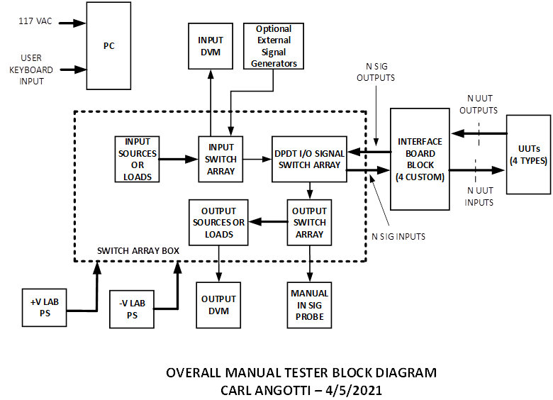
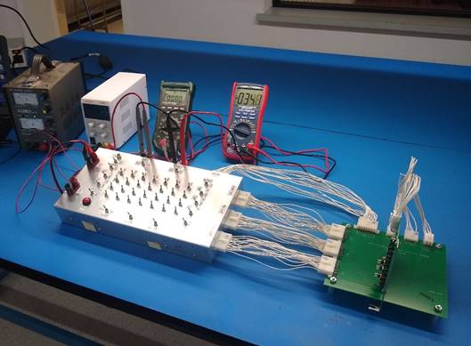
Angotti Product Deveopment Newsletter Volume 7, No. 2 (Click Here for pdf Version) "Helping You Accelerate Your High-Tech Development Projects" Welcome to the ANGOTTI PRODUCT DEVELOPMENT e-mail newsletter! The goal of this newsletter is to help you accelerate your development projects by sharing many of the tips, techniques, and strategies we've honed during three decades of providing high-tech consulting services. A Manual Tester Designed for Final Production By Carl Angotti, Angotti Product Development, https://www.angotti.com Executive Summary This article discusses the use and design of a Production Manual Tester. The simplest form of such a tester replicates the testing used to verify the initial engineering design to produce a production tester. Such a tester solidifies the testing done to verify and validate the original design. Reasons for selecting this approach Such a test approach is warranted if the Unit Under Test (UUT) has very few inputs and outputs. In this case, the production tester can consist of more rugged connectors to interface to the UUT for quick setup and tear down. The connectors make fixed connections to the needed test equipment, perhaps along with a simple switch matrix to connect inputs and outputs. A tester of this type often consists of special cables with "connector savers" that interface directly to the UUT to keep them reliable despite lots of use. The main feature that dictates that the tester is a manual one is the Operator's requirement of a manual tester because the Operator sets up the tests and then reads and interprets the results. Such human intervention in the testing process risks a higher level of error and inaccuracies that can produce significant test accuracy errors. These errors by the Operator lower the quality of the test's results. After the final product hardware design is completed, a written procedure is necessary to guide the testing personnel to complete a production manual tester. This procedure consists of a step-by-step sequence to guide the person performing the test. Manual test results are recorded on paper checklists or blank procedure spaces to record measured data. These are collected in a special notebook to be referred to later for quality control purposes. A more advanced version of a manual tester that solves some of the drawbacks of this previous type of manual testing can be designed by a test engineer. It is beneficial for testing multiple but similar UUTs. Such a tester is discussed in the next section of this article. Description of an Example Manual Tester This example tester was designed to meet the needs of a specific client. It was designed to test four different Boards that have a maximum production rate of 15 per month. The boards utilize optoisolators with many I/O channels. It also has some miscellaneous analog circuitry on all boards. A special test box was designed to minimize the overall cost. The box contains a universal set of input signals, output signals, and a 27 by 3 array of DPDT matrix switches. This tester arrangement allowed for the connection of all points via a universal set of four 36 pin connectors. After this, a custom I/O interface board was designed to perform the custom pin swapping from the universal connectors to the UUT connectors. Operator readouts were done via two auto-ranging DVMs, one monitoring input current or voltage and one measuring output current or voltage. A standardized test procedure facilitated the testing via a unique piece of software that guided the testing. This software allowed the Operator to indicate pass or fail. A unique input text file was generated to guide test steps. This input text file utilized a small set of script commands to serve as the procedure. The test results were then recorded in an archival output file for later review. Manual Tester Block Diagram The block diagram below illustrates the system interconnections at the block diagram level. Note that it contains several switch arrays inside the switch array box. There is an input array to select voltage, current, or load sources. These are switched into a bus on the one common side of a DPDT switch array. The DPDT array also controls an output array that is common to the Output / Load switch array. Throwing a switch connects the common bus input or output line to both one input and one output simultaneously. These, in turn, connect to a set of grouped input connectors and a set of output connectors. The input/output connectors connect into a pin for a pin-compatible set of similar connectors on the custom interface card connector. The interface card connects these connectors to the appropriate connectors on the UUT. The user selects a switch to a specific input and output to place the input signal into the UUT and route the output signals from the appropriate output. These inputs and outputs are then routed via the UUT interface card to the appropriate pins on the UUT. Illustration of the UUT under Test A picture of the actual UUT PCB assembly under test using the actual tester is shown below. Manual Testing the UUT The unit under test sequence using a Universal Basic test code executable is described here. Testing is accomplished utilizing a unique PC test control program. The test process is described in this section. When the program starts, the program opens a window on the PCB. The program requests the name of the Operator and the PCB serial number on the PC screen. After this, PCB testing proceeds by opening an input text file. Test instructions are presented to the Operator, and the results appear on the PCB monitor. They are presented with the Pass/Fail criteria. The Operator then checks the results on the two DVMs and responds to the test pass/fail status. This response is then recorded on an output test archive file. After this, the subsequent instructions are presented, and the process continues until all of the tests are completed. A snippet of the output file follows a snippet of the input test code for the PCB.. Input Test Code Snippet The snippet below illustrates the form of the Input file commands from the text file that controls the program via the PC executable. It illustrates the simplicity of entering tests used by the Operator for manual testing. This text file is the formalized Test Procedure that the Test Engineer creates. The code is broken into Sections (Groups) that can be skipped by the Operator if desired to advance more quickly to a particular set of tests. To make the input text more understandable, comments were added to the actual procedure file. These comments appear in the snipped example below just to the right of the "<<. " Note: A complete set of test script commands is available by emailing carl@angotti.com.. '4/7/21 - InputFile3 Open
<< Printed Comment to Operator
' *************************** ' Start Formal Board Testing ' All Tests Do Not Use Com Port '**************************** CC Check to see if ComPort is Open << “CC” is a Special Test Sometimes Required to support testing '**************************** 'Test the XY 16880 Board 'Uses a Semi-Automatic Manual Test Approach C To Continue Press Enter << “C” Stops testing to allow user to read instructions before going on '************************************* # Section 1 Input Current Limit Tests << “#” is the Start of a Test Section of a series of Tests '************************************* 'Use the Test Setup in Appendix 3 of the 'Test XY 16880 Procedure ? Is the Testing Setup OK? << “?” Asks a Question of the Operator '**************************** # Section 2 '**************************** 'Check PS1 Current Limit per 'test procedure 'Adjust Voltage to +12 V ? Is Current limit 150 to 180 mA? ' >>>>>>>>> 'Test PS2 Current Limit per 'test procedure 'Adjust Voltage to +12 V ? Is Current limit 150 to 180 mA? '**************************** # Section 2 '**************************** '+45V LED Test OK? ? '**************************** # Section 3 '**************************** '-12 V LED Tests OK? ? Is the Test Result OK? '+5V PWR Tests OK? ? Is the Test Result OK? '+12 V PWR LED Tests OK? ? Is the Test Result OK? ' +12V T & V PWR Tests ? Is the Test Result OK? >> Intermediate Tests in the procedure '**************************** # Section 7 END OF TAPE SENSOR Tests '**************************** 'END OF TAPE SENSOR Tests #1 OK? ? Is the Test Result OK? 'END OF TAPE SENSOR Tests #2 OK? ? Is the Test Result OK? 'END OF TAPE SENSOR Tests #3 OK? ? Is the Test Result OK? 'END OF TAPE SENSOR Tests #4 OK? ? Is the Test Result OK? @ Test 25 'End of Testing - Available commands are: ' P(rev) - Run Previous Test << Messages to Test Operator 'Y(es) Finish Testing this UUT 'N(o) Finish testing this UUT (not recommended) ? ' / >>>> END TESTING THIS UUT <<<<< << “/” indicates the End of Testing Output Test Code Snippet The snippet below illustrates the Output (Archival) file generated by the PC executable from the input file as testing proceeds. It illustrates what such a file might look like in practice during manual testing. Again, to make the input text more understandable, comments were added to the actual procedure file. These comments appear in the snipped example below just to the right of the "<<. " " '4/7/21
Test Menu File
'Start Testing Menu - InputFile0 ' *************************** << Menu Presented to the Operator ' Input Selection Menu ' 0 = Opening Menu - This One ' 1 = XY 15922 Board Test ' 2 = XY 16669 Board Test ' 3 = XY 16680 Board Test ' 4 = Not Available '**************************** 'Select Input Number Desired '**************************** 'After Last Board is Tested 'Quit this Program ' *************************** ' Select a New File you want to open << Operator select Input File % Get File # and Open << Command to Open the file Selected Test Person's Name is: John Jones <<Name of Test Person entered ********************************************************* >> Printed to the * Beginning of Testing * >> Archive File * 04/07/21 06:39:41 * >> via Executable * UUT S/N = 1 * ********************************************************* '4/7/21 - InputFile 1 Open << Indicates which file was opened '*************************** 'Start Formal Board Testing >> Message sent to Operator 'All Tests Do Not Use Com Port '**************************** CC Check to see if ComPort is Not Open >> Message sent to Operator '**************************** 'This program performs Test on the XY 15922 Board 'This Semi-Automatic Test Procedure assists with 'accurate test flow and QA logging. 'It is used with the companion Test Procedure. C To Continue Press Enter @001 - Test 1 '************************************* '************************************* ' Use the Test Setup in Appendix 3 of the ' XY 15923 Test Procedure ? Is the Testing Setup OK? **************************************************** >> Test Passed >>>>>>>>>>>>>>>> Test OK <<<<<<<<<<<<<<<<<< * >> Printed to the **************************************************** >> Archive File '**************************** '**************************** @002 - Test 2 'Check PS1 Current Limit per 'test procedure Step General Test 'Turn DVM1 Switch to VOLT, Turn S1 ON 'Adjust Voltage to +12 V, Set Current Limit ? Is Current limit 150 to 180 mA? **************************************************** >>>>>>>>>>>>>>>> Test OK <<<<<<<<<<<<<<<<<< * **************************************************** 'Turn S1 OFF ' @003 - Test 3 ' >>>>>> Next Power Supply <<<<<< 'Test PS2 Current Limit per 'test procedure 'Turn DVM1 Switch to VOLT, Turn S2 ON 'Adjust Voltage to +5 V, Set Current Limit 'Turn S2 OFF ? Is Current limit 150 to 180 mA? **************************************************** >>>>>>>>>>>>>>>> Test OK <<<<<<<<<<<<<<<<<< * **************************************************** '**************************** '**************************** @004 - Test 4 ' USE EXTREME CAUTION DURING THIS TEST ' +45 Volt Test Step 1 ' Perform Test per Procedure ' Turn DVM1 Switch to VOLT, Turn S1 ON ' Adjust Voltage to +45 V ' Turn DVM Switch to Current ' Turn Matrix A1 ON, L1 ON ' PB OFF - DVM1 = 28-32V, DVM2 = 70-80mV ' PB ON- DVM1 = 90-110mV, DVM2 = 112-122mv ? >>> The Operator Stopped Testing at this point Expanding the System I/O The system can have further expandable Input or Output Sources or Loads by adding an expansion input or output box. These signals are connected to another pair of switches located on the main switch box. These switches permit signals up to about 100KHz bandwidth to be input to or read from the large switch array. These I/O channels might be connected to another expansion switch box that accomplishes the additional switching required to select multiple added inputs and outputs beyond those provided. Summary of this Article This article discusses how an inexpensive and
practical Manual Tester can be created to meet the needs of many
manually operated Functional Test requirements. Such a tester can be
produced at a much lower cost and made more quickly available than
constructing a new single-purpose custom tester. |
|||||
|
Angotti Product Development
|
||||||